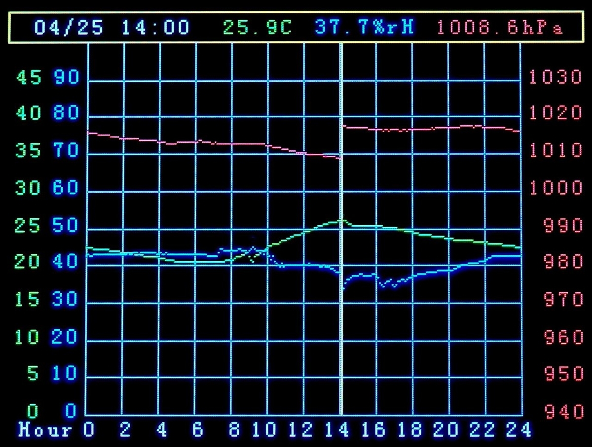
特別な工夫はないのですが(^^;、小さな画面にグラフ表示して過去1日の変化を示す気象計です。今14時ちょうどですが、昨日の今に比べてずいぶん気圧が下がったのに気づきます。これだと今晩雨が降るかもしれませんね。
昨日から2階の和室に1日置いたのですが、窓や入口の開閉に応じて温度や湿度が少し上下します。
こういう気象計が売られているのは見かけませんが、この表示方法がほかの工作にも応用できそうなので記事にするとします。前に書いたCO2濃度計(右のカテゴリーのCO2測定から参照してください)やガンマ線表示計(同じくガイガーカウンターから)などで、この表示ならかなり便利そう。それらは時間ができたらやってみるとして。
この表示を試したのは単純なきっかけからです。マイコンの容量と速度が増し、Teensy4.0などもArduino-IDEに対応して手軽に使える有難い時代になりました、これまでのESPもですが。Raspberry Pi Picoは少し試した限りではArduino-IDEとの相性が今一つですが。
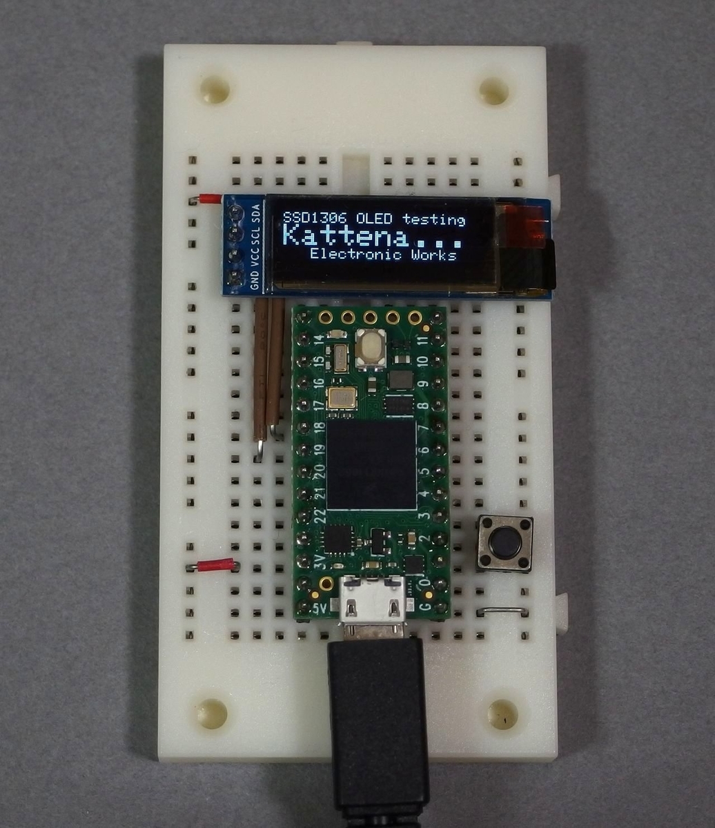
ともあれ、そういうマイコンの表示はGraphicsディスプレイにしたいものです。そこで見易いOLEDを5種類ほど試してみましたが、簡単な用途向けではサイズがまだまだ小さくて拡大鏡が必要ですね・・^^; 下の写真はTeensy4.0にSSD1306OLEDをつないでみたもの。
表示装置付きのM5-stackを使うのも便利ですが、テストでなく組み込むには無理があるし。。。
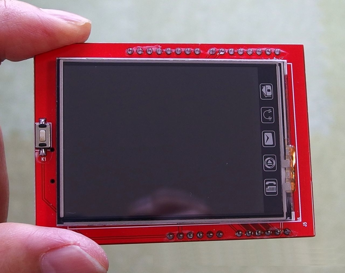
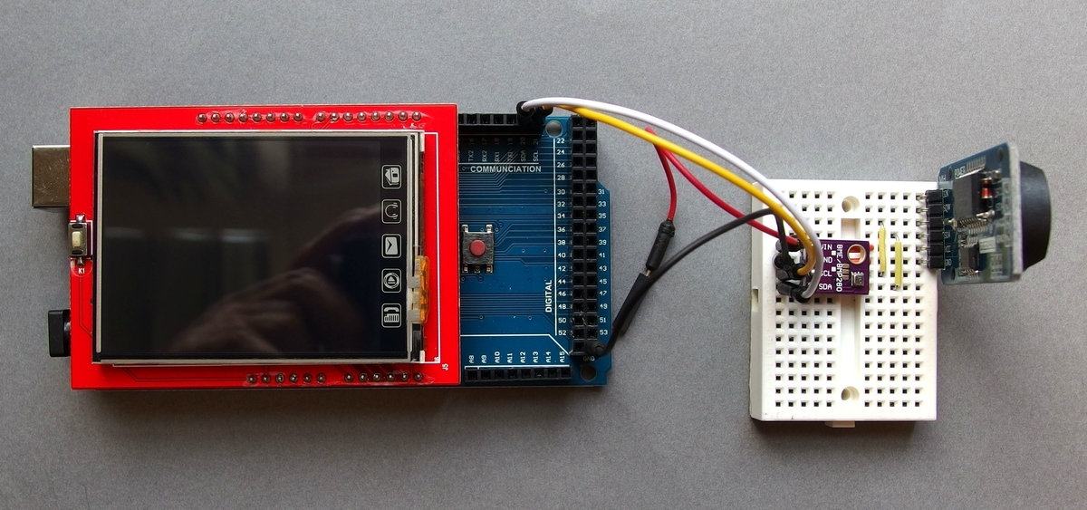
もう少し大きい表示装置が何かないかなーと手持ちの部品を漁り、このTFTカラー液晶シールドに気づきました。mcufriendとシルク印刷された2.4インチの表示器で、かつてArduino-Unoで使っていました。なぜかUnoのピンをほぼ全部塞ぐだけでなくUNOの容量が次第に不足気味となりもはや用済み、部品箱で長らく眠っていたのでした^^
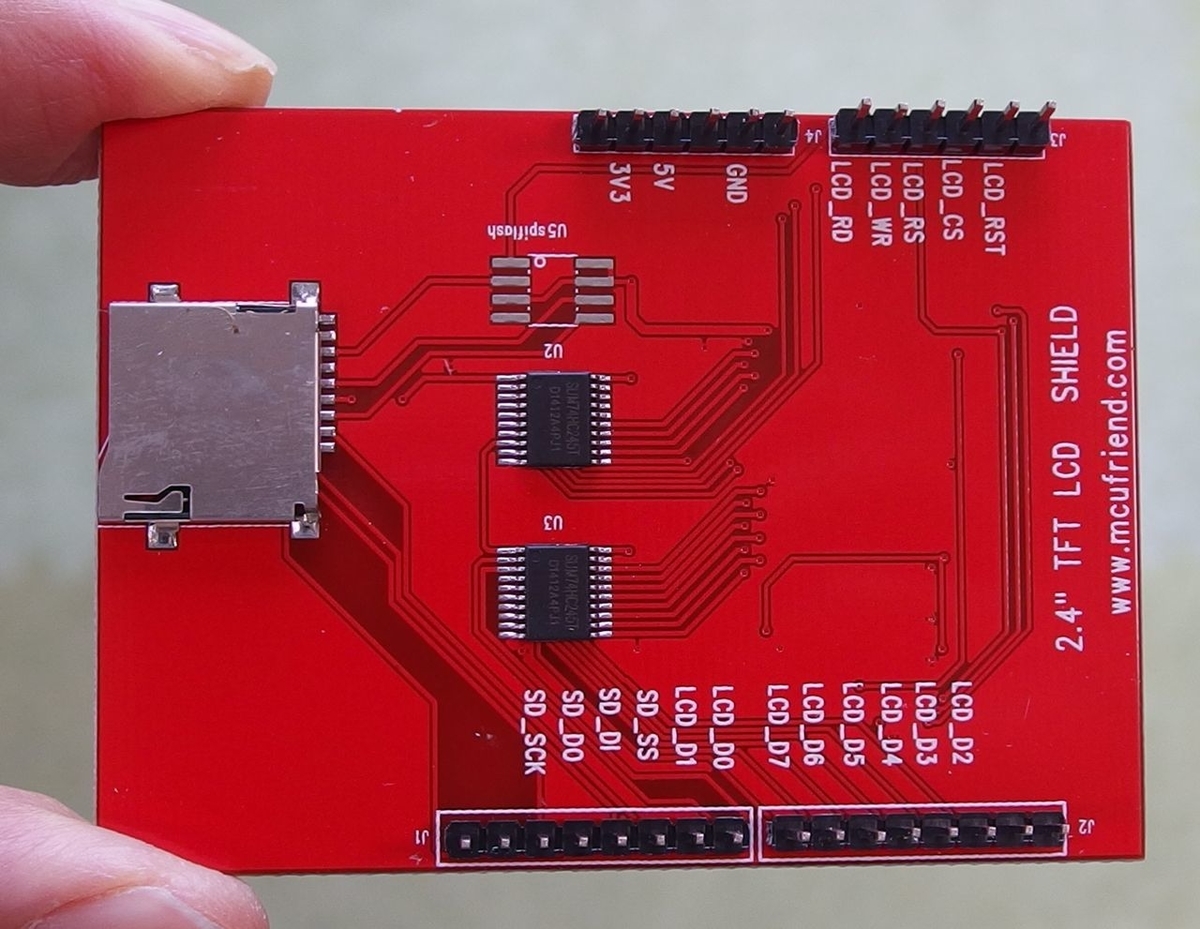
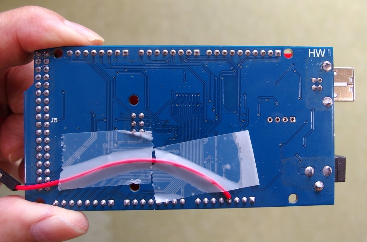
裏は次です。
480x320ピクセルのカラー2.4インチ。それならいいかも!・・・。
ただし、これはUNOに合わせたシールドなのでピンが扱いにくい。そこで思いついて、まずはArduino-Megaに挿してみました。内蔵のマイクロSDを使うには少し問題があり、該当ピンがUNOのSPI接続にとられるため、その4本のピンをカットしてMEGAのSPI各ピンに配線でつなぐのがよいかと思われます。とりあえずはこれを無視して放置し、表示だけをテストすることにしました。このシールドをMEGAに次のように取り付けます。
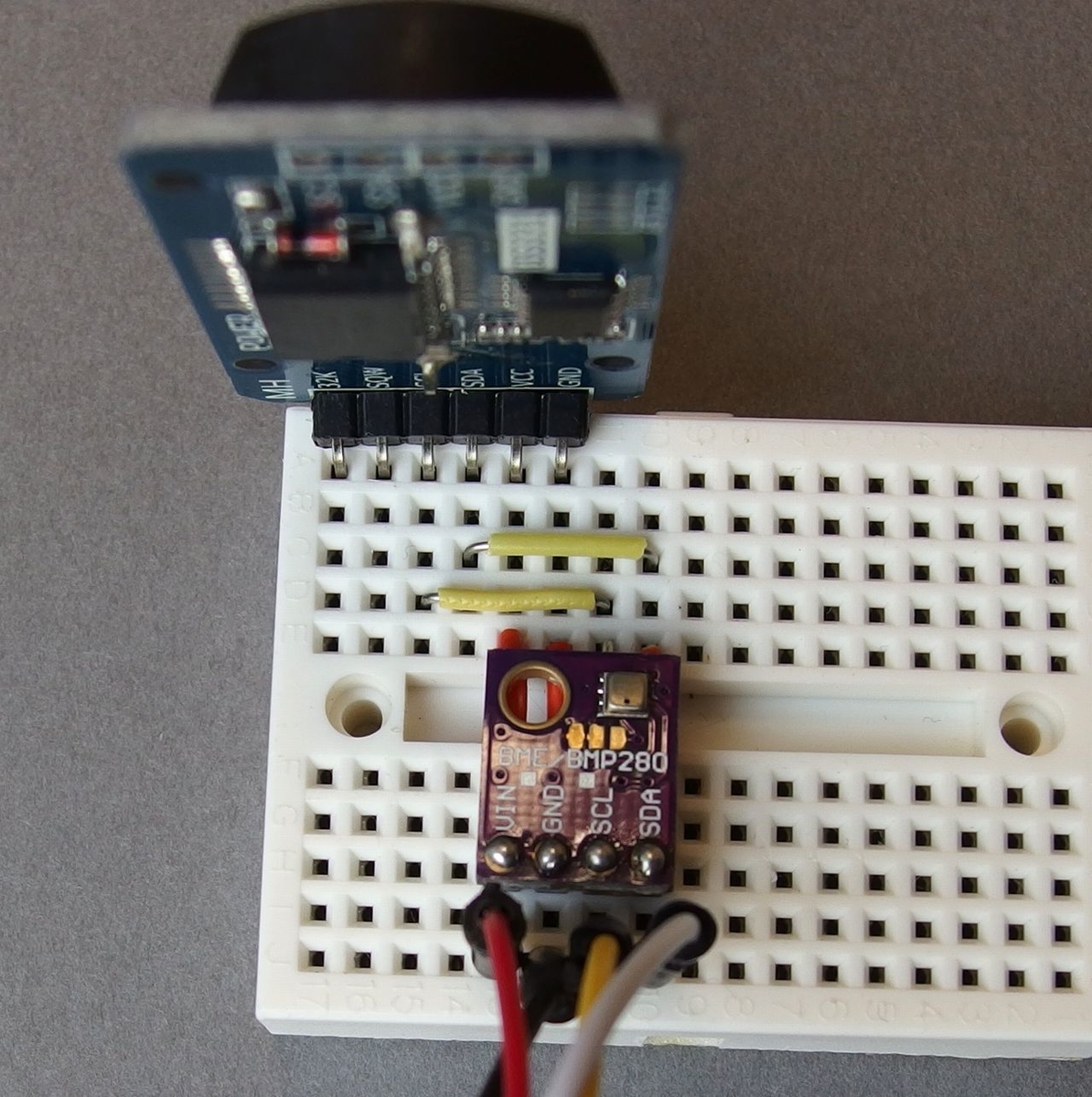
そしてセンサーとRTC(リアルタイムクロック)と配線した部分は次です。
このようにするとArduinoからの3.3V出力もふさがってしまうので、裏面から配線で取り出しています。
そしてプログラムを作りますが、まずはArduinoの普通のTFT-LCDライブラリーではうんともすんとも^^; いったいどんな接続だったっけな(・・?
この製品に書いてあるmcufriendをググってみるとMCUFRIEND_kbv libraryライブラリーにたどり着きます。Arduinoのモデルを選ばないオールマイティとか。それを使ったらなんと即、問題なく動きました。
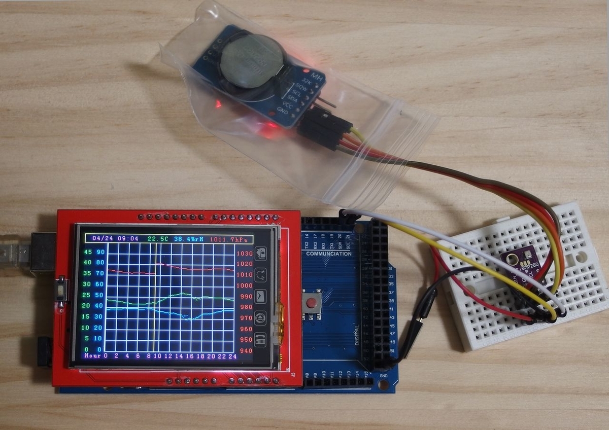
1日放置したのが上の写真ですが、大きさも鮮明さも良い感じです。測ると電流を200mAほど消耗しているのにはびっくりですが。プログラムは色使いや位置等を少し調整して冒頭に掲げた画面を出しているのが次のスケッチです。作るのと改訂に半日以上使ってしまいましたが。
/****************************************************************
  Weather station with TFT-LCD 320x240 & BME280 -  V.02
    Initial version V.01 on Apr.18,2021   (c) Akira Tominaga
  Function:
    Display temperature-C, relative humidity-% & pressure-hPa.
    24-hour-plot wraps round every 24 hours.
  Pin connections:
    TFTLCD shield(MCUFRIEND_kbv) attached to Arduino-MEGA.
    Arduino-Mega 3.3V,G,SDA&SCL to sensor&RTC's VCC,G,SDA&SCL.
  Revisions:
    V01: Changed design of grid and position-marker.  4/19/2021
    V02: Minor changes to characters and some colors. 4/23/2021
  Remarks:
   Librarie's licensing rules & (c)s are attached in the bottom.
  **************************************************************/
#include "UTFTGLUE.h"     // MCUFRIEND_kbv library
#include "Wire.h"         // I2C for RTC-DS3231 and BME280
#include "Adafruit_Sensor.h"
#include "Adafruit_BME280.h"
// *** for LCD ***
UTFTGLUE lcd(0, A2, A1, A3, A4, A0);
#define wW 320            // TFT width
#define hH 240            // TFT height
#define bX 43             // x @ begin-graph
#define eX wW-36          // x @ end-graph(284 in this case)
int lX = (eX - 1) - (bX + 1) + 1; // x-axis len (240 this case)
#define bY 18             // y @ begin graph
#define eY hH-15          // y @ end graph
// *** for colors ***
#define White (192,192,192)
#define Black (0,0,0)
#define Red (255,48,48)
#define Green (0,255,0)
#define Blue (0,100,255)
#define Yellow (255,255,0)
#define Purple (255,0,255)
#define rGray (127,127,127)
#define dGray (32,32,64)
// *** for application use ***
char Temp[] = "xx.xC";    // 5+1 bytes for temperature
char rH[] = "xx.x%rH";    // 7+1 bytes for relative humidity
char hPa[] = "xxxx.xhPa"; // 9+1 bytes for pressure
#define iniX bX+1         // graph initial x-position
#define lastX eX-1        // graph last x-position
uint16_t curX = iniX;     // set curX at initial position
uint16_t posY;            // position Y
// *** for measurement ***
Adafruit_BME280 bme;      // name as bme
// to keep measurement for 24hours in lX positions;
uint16_t intervalM = round(24 * 60.0 / lX); // interval minutes
uint8_t moV;              // current month
uint8_t daV;              // current day
uint8_t hrV;              // current hour
uint8_t mnV;              // current minute
uint8_t mnVsv = 99;       // former minute save area
char MDhm[] = "MM/DD hh:mm"; // editing area for clock

void setup() { // ***** Arduino setup() *****
  Serial.begin(9600);
  Wire.begin();
  lcd.InitLCD();
  lcd.clrScr();
  //////////////////////////////////////
  // *** Draw frame ***               //
  //////////////////////////////////////
  lcd.setColor Black;     // make a blackboard
  lcd.fillRect(0, 0, wW - 1, hH - 1);
  lcd.setColor Yellow;
  lcd.drawRect(0, 0, wW - 1, bY - 1); // top bar
  // *** fill texts in top bar ***
  lcd.setFont(SmallFont);
  lcd.setBackColor Black; // text's back-color
  dspVal();               // initial text in top bar
  //////////////////////////////////////
  //*** draw axes, grid and scales ***//
  //////////////////////////////////////
  // *** vertical lines and scales***
  lcd.setColor rGray;
  lcd.drawLine(eX, bY, eX, eY); // right edge (graph limit+1)
  for (uint8_t tU = 0; tU < 25; tU += 2) {
    uint16_t xL = bX + 1 + round(lX * (tU / 24.0));
    lcd.setColor rGray;
    lcd.drawLine(xL, bY, xL, eY);
    lcd.setColor White;    //
    char hhC[3];
    sprintf(hhC, "%2d", tU);
    lcd.print(hhC, xL - 8, hH - 12);
  }
  lcd.print("Hour", 8, hH - 12);
  // *** vertical scales and horizontal lines ***
#define tsMax 50          // temperature max scale
#define tsMin 0           // temperature minimum scale
#define tsStep (tsMax-tsMin)/10
#define hsMax 100         // rel. humidity max scale
#define hsMin 0           // relative hum. min scale
#define hsStep (hsMax-hsMin)/10
#define psMax 1040        // pressure max scale 1040
#define psMin 940         // pressure min scae 940
#define psStep (psMax-psMin)/10
  char tsC[4];            // chars for temperature
  char hsC[4];            // chars for rel.humidity
  char psC[5];            // chars for pressure
  int tS = tsMin;         // init. temperature scale
  int hS = hsMin;         // init. humidity scale
  int pS = psMin;         // init. pressure scale
  // draw horizontal lines and scales in a loop
  for (int g = 0; g < 10; g++) {
    int iy = round(eY - (eY - bY) * g / 10.0);
    lcd.setColor rGray;
    lcd.drawLine(bX + 1, iy, eX, iy); // horizontal line
    sprintf(tsC, "%2d", tS); // temp val. text
    sprintf(hsC, "%2d", hS); // rHum val. text
    sprintf(psC, "%4d", pS); // pres val. text
    lcd.setColor Green;   // for temperature
    lcd.print(tsC, 5, iy - 7);
    lcd.setColor Blue;    //  for humidity
    lcd.print(hsC, 26, iy - 7);
    lcd.setColor Red;     // for pressure
    lcd.print(psC, eX + 5, iy - 7);
    tS = tS + tsStep;     // increase pos. for temp.
    hS = hS + hsStep;     // increase pos. for humi.
    pS = pS + psStep;     // increase pos. for pres.
  }
  //////////////////////////////////////
  //*** prepare BME280 sensor      ***//
  //////////////////////////////////////
  if (!bme.begin()) {     // check validity of BME280
    Serial.println(F("Invalid BME280."));
    Serial.print("SensorID=0x");
    Serial.println(bme.sensorID(), HEX);
    Serial.println(F(" ID 0x56-0x58 for BMP280."));
    Serial.println(F(" ID 0x61 for BME680."));
    while (true) {}       // if error, stop here
  }
  delay(1000);            // wait sensor stabilized
}
void loop() { // ***** Arduino loop() *****
  // *** display clock and check timing to measure
#define aMomnt 1000       // mS to wait for a moment
waitTiming:
  geTime();               // get time and calendar
  if (mnV == mnVsv) {     // if no change in minute
    delay(aMomnt);        // then wait for a moment
    goto  waitTiming;     // repeat checking
  }
  // *** display clock in top bar each second
  sprintf(MDhm, "%02d/%02d %02d:%02d", moV, daV, hrV, mnV);
  lcd.setColor White;    // for Clock
  lcd.print(MDhm, 15, 4); // display date and clock
  // *** check graph-drawing timing or not
  if ((mnV % 6) > 0) {    // if not multiple of 6
    delay(aMomnt);        // then wait for a momentr
    goto  waitTiming;     // repeat checking
  }
  // *** now measurement start
  mnVsv = mnV;            //save time (min) processed this time
  uint16_t vMin = hrV * 60 + mnV; // cur. time in minute
  uint16_t xPos = round(lX * (float)(vMin / (60.0 * 24)));
  curX = bX + 1 + xPos;   // get current hilizontal position
  // *** get measured data and edit them into top bar
  uint16_t Tempx10 = round(10.0 * bme.readTemperature());
  uint8_t temp = Tempx10 / 10;  // get integer part
  uint8_t tempD = Tempx10 % 10; // remainder after dot
  sprintf(Temp, "%2d", temp);   // edit integer 2chars
  Temp[2] = '.';
  sprintf(Temp + 3, "%01d", tempD); // edit after dot
  uint16_t Humix10 = round(10.0 * bme.readHumidity());
  uint8_t humi = Humix10 / 10;  // get integer
  uint8_t humiD = Humix10 % 10; // remainder after dot
  sprintf(rH, "%2d", humi);     // edit integer 2chars
  rH[2] = '.';
  sprintf(rH + 3, "%01d", humiD); // edit after dot
  uint16_t Presx10 = round(bme.readPressure() / 10.0);
  uint16_t pres = Presx10 / 10; // get integer part
  uint16_t presD = Presx10 % 10; // remainder after dot
  sprintf(hPa, "%4d", pres);    // edit integer 4chars
  hPa[4] = '.';
  sprintf(hPa + 5, "%01d", presD); // edit after dot
  dspVal();               // show the values in top bar
  // *** draw position marker line ***
  // erase the past marked line
  lcd.setColor Black;     // with blackboard color
  lcd.drawLine(curX, bY, curX, eY - 1); // erase
  // re-mark grid positions
  lcd.setColor rGray;     // with grid color
  for (int g = 0; g < 10; g++) {
    int iy = round(eY - (eY - bY) * g / 10.0);
    lcd.drawPixel(curX, iy); // re-draw grids
  }
  // ** if on the hour line, then recover it
  if ((curX - (bX + 1)) % (round(lX / 12.0)) == 0) { // if 2hours x N
    lcd.drawLine(curX, bY, curX, eY); // recover the hour line
  }
  // *** draw measurement graphs ***
  lcd.setColor Green;     // temperature
  posY = (eY - 1) - round((Tempx10 / 10.0) * (eY - bY) / 50.0);
  lcd.drawPixel(curX, posY);
  lcd.setColor Blue;      // relative humidity
  posY = (eY - 1) - round((Humix10 / 10.0) * (eY - bY) / 100.0);
  lcd.drawPixel(curX, posY);
  lcd.setColor Red;       // pressure
  posY = (eY - 1) - round(((Presx10 / 10.0) - 940) * (eY - bY) / 100.0);
  lcd.drawPixel(curX, posY);
  // increase x-position for next measurement
  curX++;                 // get next position
  if (curX > lastX) {
    curX = iniX;
  }
  /// *** draw vertical marker line ***
  lcd.setColor Yellow;    // with Yellow color
  lcd.drawLine(curX, bY, curX, eY - 1);
} // *** end of Arduino loop() ***
/**************************************************
    User defined functions
 **************************************************/
// ***** dspVal() *** display values measured *****
void dspVal(void) {
  lcd.setColor Green;     // for temperature C
  lcd.print(Temp, 120, 4);
  lcd.setColor Blue;      // for relative humidity %
  lcd.print(rH, 171, 4);
  lcd.setColor Red;       // for pressure hPa
  lcd.print(hPa, 238, 4);
}
// *** geTime() *** get month,day,hr & min from DS3231
void geTime(void) {
#define aRTC 0x68       // RTC I2C addr
#define mdm 2           // minute position in RTC data
#define mdh 3           // hour position in RTC data
#define mdD 5           // day position in RTC data
#define mdM 6           // month position in RTC data
  byte  vR[8];          // values in RTC format
  Wire.beginTransmission(aRTC);
  Wire.write(0x00);
  Wire.endTransmission();
  Wire.requestFrom(aRTC, 7);
  while (Wire.available() < 7) {}  // wait for data
  for (int i = 1; i < 8; i++) {
    vR[i] = Wire.read();
  }
  Wire.endTransmission();
  moV = ((vR[mdM] & B00010000) / 16) * 10 + (vR[mdM] & B00001111);
  daV = ((vR[mdD] & B01110000) / 16) * 10 + (vR[mdD] & B00001111);
  hrV = ((vR[mdh] & B00100000) / 32) * 20 + ((vR[mdh] & B00010000) / 16) * 10 + (vR[mdh] & B00001111);
  mnV = ((vR[mdm] & B01110000) / 16) * 10 + (vR[mdm] & B00001111);
}
// Library providers' copyrights and lisences are as follows:
/************* UTFTGLUE library *********************************
   TFT-LCD 320x240 pixels.
    MCUFRIEND_kbv (C)2015 Rinky-Dink Electronics, All rights
    reserved.   web: http://www.RinkyDinkElectronics.com/
****************************************************************/
/**** for Adafruit-GFX-Library used by UTFTGLUE *****************
  Software License Agreement (BSD License)  (c) 2012 Adafruit
  Industries, All rights reserved. Redistributions in binary form
  must reproduce copyright notice. See BSD lisence conditions.
***************************************************************/
/***********ふFor Adafruit_BME280 ******************************
  Designed specifically to work with the Adafruit BME280
   http://www.adafruit.com/products/2650
  Use I2C or SPI interface. I2C adrs is 0x76 or 0x77. Adafruit
  invests time and resources providing this open source code,
  please support Adafruit and open hardware by purchasing
  products from Adafruit!
  By Limor Fried & Kevin Townsend for Adafruit Industries.
  BSD license: all above must be included in any redistribution.
  See LICENSE file for details in the library.
*****************************************************************/
// end of programピンをよく確認して、これを他のマイコンで動かすのにチャレンジしてみたいと思います。電流が多いので電源の与え方に注意しないといけないかも。。。
と考えたのですが、現在は似た製品が海外ネットで色々出回っていますね。タッチパネルでなければ価格も1000円未満で手ごろそうです。省エネなども少しは改善されたことでしょう。いっそ、そちらを入手して試してみる方がいいかな・・早速今注文してしまいました^^
2021.4.26追記 ================================
今回使用したTFT-LCDのピンの記述を調べた結果、次のものと完全に同じです。
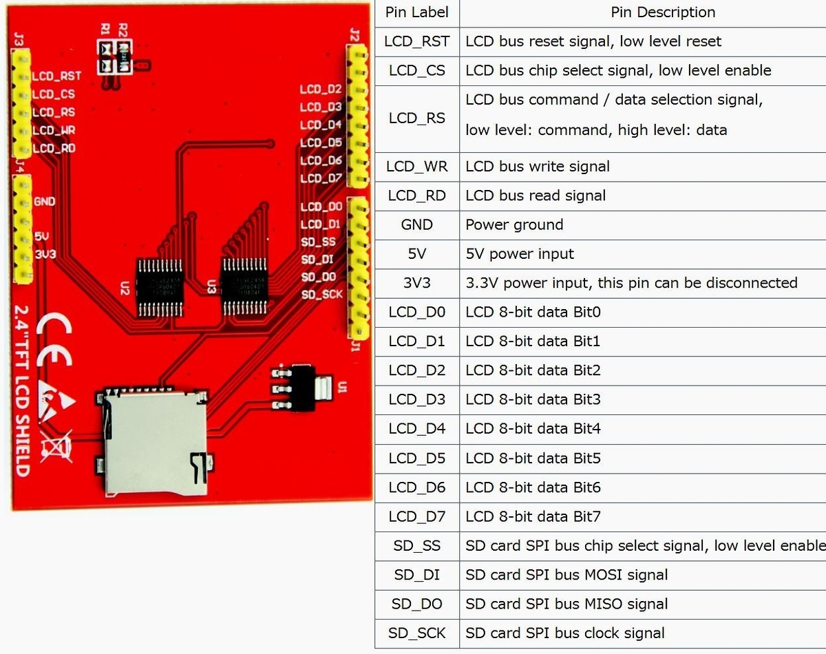
同型の一般的な製品ではMCUにILI9341が使われているようですが、MCUFRIENDのこのTFT-LCDシールドではILI9320が使われています。それがMCUFRIENDのライブラリーを必要としている理由かなと推察。
ついでに、動作中の接続状態を調べたらSD用の4本(上の表で下4つ)以外はすべて使用しており、Arduinoとのデータのやりとりは8ビットパラレルです。表示速度は速いですが、マイコンの限られたピンを15本消耗するのは厳しい^^;。節約してもせいぜい-4本(電源を外部供給、RSTをHIGHにしCSをLOWにして固定)、それでも11本は表示用にとられます。そのうちに、目的であるTeensyで試そうと思ってはいます。。。
そういうわけで、今回注文したものはSPI接続だけででき、画面サイズがもう少し大きな3.5インチにしました。例によって到着までに数週はかかるでしょうが、ボチボチやるのでちょうどいいかもしれません。
================================== 追記end
以上、簡単に書かせていただきましたが、何らかのお役に立てば幸いです。
©2021 Akira Tominaga, All rights reserved.