
LCDキャラクター・ディスプレイは余り使われなくなってきたかもしれませんが、廉価で、OLEDと比較にならないほど容量を食わず、今でも電子工作に重宝なデバイスだと思いますがどうでしょう?
多くのマイコンでは標準ライブラリーがあり、I2Cで楽に接続できるという点、それに海外ネットで廉価で出回っている点も助かります。そういうわけで、私はESPやArduinoなどではこれをしばしば使うので手持ちが沢山あります。16桁2行と20桁4行が普通で、私の持っているのは1個あたりそれぞれ200円、400円ぐらいでした。
確認のために今eBayをちらとみると次です。もっと廉価なのも多いかもしれませんし、Aliでも廉価なものが多いだろうなと思います。表示色は青に白字が多いですが、黄色や緑に黒字、あるいは緑に白字などもあります。ただしI2C接続でないものもありますから注意が必要です。

LCD自体は相当古い日立のHD44780Uドライバーで動かす、日立液晶ディスプレイのコンパチ機です。それにTIのPCF8574(I2Cパラレルポート・エキスパンダーIC)または同等ICを接続して、I2Cで簡単に動くようになっているものです。
LCD自体は今でも日立との互換LCDであるというところがすごい!どれにも基本的には日立のA00という文字セットが含まれ、多数使われている海外でも、なんとカタカナを表示するところがとてもおかしいのですが^^;
古い日立のデータシートを見ると内蔵文字の基本パターンは次です。
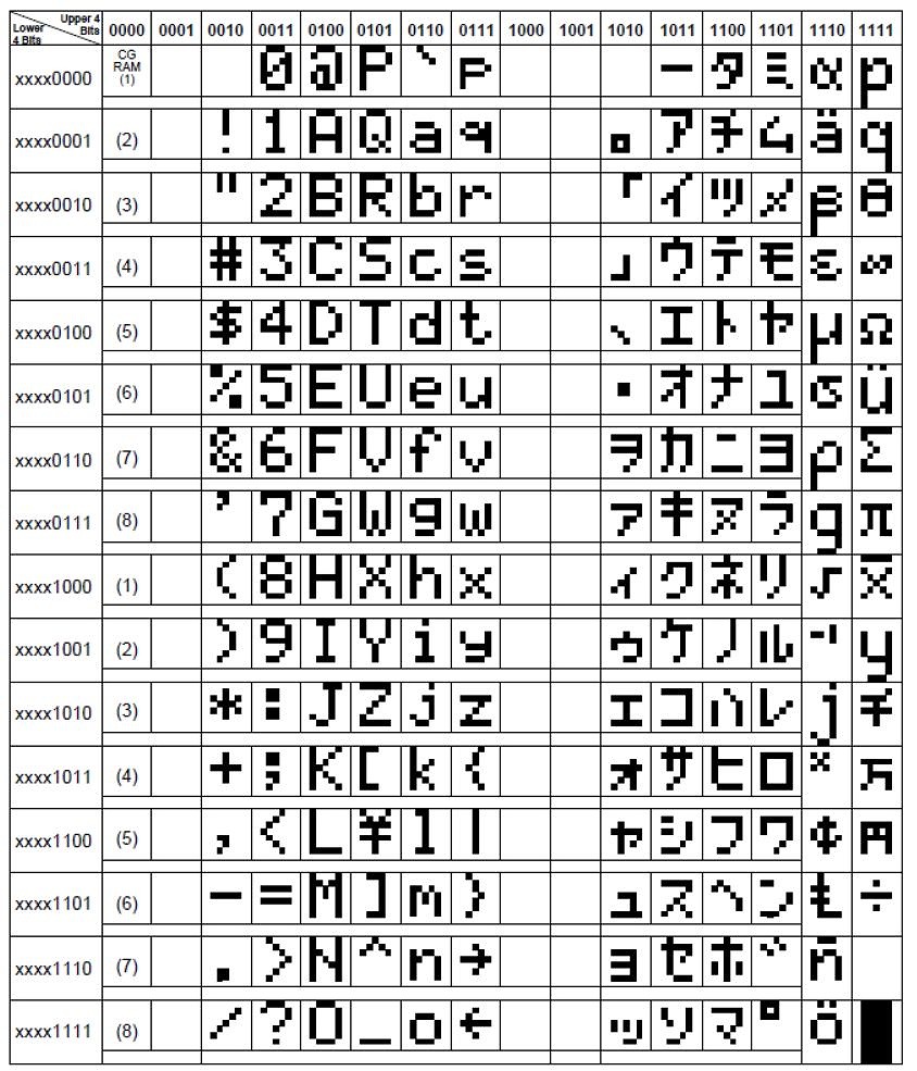
海外通販で購入したもので全文字を表示してみたら、次のようになっています。

全部比較すると日立のと完全に同じですね!
これを表示したときの簡単なテストの様子は次の写真です。

Arduinoでは標準的なLiquidCrystalライブラリーを、New_LiquidCrystal_I2Cライブラリーで置き換えることで最近の型も動作します。前に次の記事の最後に書き足したかと思います。。
マイコンとPCのデータ授受ーSmallbasicなら簡単 (2020.12.05 LiquidCrystal_I2Cについて補足しました) - 勝手な電子工作・・
ところが、このLCDのイニシャライズの中身は理不尽なほど複雑です^^; かつデータはドライバーから4ビットパラレル接続となっているため、ライブラリーなしで直接扱うときは1文字を2回に分けて送る必要があったりします。つまりプロトコルも輪をかけて複雑に。
今回はこの廉価なLCDを小さな8ピンPICに簡単につなぐ挑戦です。いつかはPICにつなごうと思っていましたが、他のI2Cデバイスはともかくも、このLCDだけは上に書いたような理由でコードの手書きは敬遠していました。
しかし、この週末にPICでの手作りを遂にやってみました!
今回のPICは5~6年前に1個60円ほどで大量購入した12F1822なのですが、手元に残っているので利用。今見ると秋月では110円に値上がりしたようですね。もちろん8ビットPICならどれでもほぼ大丈夫と思います。
この小さなPICはプログラムメモリーが2Kしかなく、RAMはわずか128バイトしかありません。しかし16MHzクロックで動きPIC Assemblerで書けばかなりのことができる優れものです。周辺装置の役割として何にでも便利に使っています。ライブラリーを使わない場合は容量は十分です。
まずは複雑プロトコルを解析するために、使う機能だけを選んでArduinoでごく簡単なテストをします。次のスケッチです。
/**********************************************************
      Simple test-A for protocol analysis
                        Dec. 19, 2020  by Akira Tominaga
           Remarks: Use Arduino, ESP32, or ESP8266 etc.
                    Connect SCL and SDA to LCD-I2C pins.
***********************************************************/
#include "LiquidCrystal_I2C.h" // New_LiquidCrystal_I2C library
#define i2cA 0x27           // LCD's I2C address
// addr, LCD-pins, BL  addr,en,rw,rs,d4,d5,d6,d7,bl,blpol
LiquidCrystal_I2C lcd(i2cA, 2, 1, 0, 4, 5, 6, 7, 3, POSITIVE);

void setup() { // ***** Arduino setup *****
  delay(10);

  // case #1 lcd.begin
  lcd.begin(20, 4);
  delay(300);

  // case #2 lcd.backlight() (unneeded?)
  lcd.backlight();
  delay (200);

  // case #3 lcd.clear
  lcd.clear();              // clear LCD
  delay(100);

  // case #4 cursor  line 3 ,col 15
  lcd.setCursor(15, 3);
  delay(200);

  // case #5 cursor line 2 ,col 8
  lcd.setCursor(8, 2);
  delay(300);

  // case #6 cursor line 1 ,col 5
  lcd.setCursor(5, 1);
  delay(200);

  // case #7 cursor line 0 ,col 0
  lcd.setCursor(0, 0);
  delay(100);

  // case #8 lcd.print
  lcd.print("ABC");
  lcd.print("123");

  while (true) {}         // stop here
}

void loop() { // ***** Arduino loop *****
  // do nothing
}

Decode結果は次のとおりです。
Time [s]	 Decoded Protocol Result
0.00000925	Setup Write to [0x4E] + ACK
150μS	1)
0.00014925	Setup Write to [0x4E] + ACK
0.0002445	0x00 + ACK
100mS	2)
0.10040025	Setup Write to [0x4E] + ACK
0.1004955	0x34 + ACK
0.10063475	Setup Write to [0x4E] + ACK
0.10073	0x30 + ACK
5mS	3)
0.105399	Setup Write to [0x4E] + ACK
0.10549425	0x34 + ACK
0.1056335	Setup Write to [0x4E] + ACK
0.10572875	0x30 + ACK
250μS	4)
0.106023	Setup Write to [0x4E] + ACK
0.106118	0x34 + ACK
0.10625725	Setup Write to [0x4E] + ACK
0.1063525	0x30 + ACK
250μS	5)
0.1066465	Setup Write to [0x4E] + ACK
0.10674175	0x24 + ACK
0.10688075	Setup Write to [0x4E] + ACK
0.106976	0x20 + ACK
250μS	6)
0.10727025	Setup Write to [0x4E] + ACK
0.1073655	0x24 + ACK
0.1075045	Setup Write to [0x4E] + ACK
0.10759975	0x20 + ACK
0.10774875	Setup Write to [0x4E] + ACK
0.107844	0x84 + ACK
0.10798325	Setup Write to [0x4E] + ACK
0.10807825	0x80 + ACK
200μS	7)
0.1082825	Setup Write to [0x4E] + ACK
0.10837775	0x04 + ACK
0.10851675	Setup Write to [0x4E] + ACK
0.108612	0x00 + ACK
0.10875625	Setup Write to [0x4E] + ACK
0.10885125	0xC4 + ACK
0.1089905	Setup Write to [0x4E] + ACK
0.10908575	0xC0 + ACK
150μS	8)
0.10922975	Setup Write to [0x4E] + ACK
0.109325	0x04 + ACK
0.10946425	Setup Write to [0x4E] + ACK
0.1095595	0x00 + ACK
0.1097035	Setup Write to [0x4E] + ACK
0.10979875	0x14 + ACK
0.109938	Setup Write to [0x4E] + ACK
0.11003325	0x10 + ACK
2mS	9)
0.11219225	Setup Write to [0x4E] + ACK
0.1122875	0x04 + ACK
0.11242675	Setup Write to [0x4E] + ACK
0.11252175	0x00 + ACK
0.112666	Setup Write to [0x4E] + ACK
0.11276125	0x64 + ACK
0.11290525	Setup Write to [0x4E] + ACK
0.1130005	0x60 + ACK
150μS	10)
0.11313975	Setup Write to [0x4E] + ACK
0.113235	0x08 + ACK
300mS	lcd Backlight
0.4133845	Setup Write to [0x4E] + ACK
0.41347975	0x08 + ACK
200mS	lcd Clear
0.6136425	Setup Write to [0x4E] + ACK
0.61373775	0x0C + ACK
0.613877	Setup Write to [0x4E] + ACK
0.61397225	0x08 + ACK
0.61411625	Setup Write to [0x4E] + ACK
0.6142115	0x1C + ACK
0.61435075	Setup Write to [0x4E] + ACK
0.614446	0x18 + ACK
	Set cursor 15,3
0.716622	Setup Write to [0x4E] + ACK
0.71671725	0xEC + ACK
0.7168565	Setup Write to [0x4E] + ACK
0.71695175	0xE8 + ACK
0.717096	Setup Write to [0x4E] + ACK
0.71719125	0x3C + ACK
0.7173305	Setup Write to [0x4E] + ACK
0.7174255	0x38 + ACK
	Set cursor 8,2
0.9175885	Setup Write to [0x4E] + ACK
0.91768375	0x9C + ACK
0.917823	Setup Write to [0x4E] + ACK
0.91791825	0x98 + ACK
0.91806225	Setup Write to [0x4E] + ACK
0.9181575	0xCC + ACK
0.91829675	Setup Write to [0x4E] + ACK
0.918392	0xC8 + ACK
	Set cursor 5,1
1.2185565	Setup Write to [0x4E] + ACK
1.21865175	0xCC + ACK
1.218791	Setup Write to [0x4E] + ACK
1.21888625	0xC8 + ACK
1.2190305	Setup Write to [0x4E] + ACK
1.21912575	0x5C + ACK
1.21926475	Setup Write to [0x4E] + ACK
1.21936		0x58 + ACK
	Set cursor 0,0
1.419528	Setup Write to [0x4E] + ACK
1.419623	0x8C + ACK
1.41976225	Setup Write to [0x4E] + ACK
1.4198575	0x88 + ACK
1.42000175	Setup Write to [0x4E] + ACK
1.420097	0x0C + ACK
1.42023625	Setup Write to [0x4E] + ACK
1.4203315	0x08 + ACK
	write "ABC123"
1.5204875	Setup Write to [0x4E] + ACK
1.52058275	0x4D + ACK
1.520722	Setup Write to [0x4E] + ACK
1.520817	0x49 + ACK
1.52096125	Setup Write to [0x4E] + ACK
1.5210565	0x1D + ACK
1.52119575	Setup Write to [0x4E] + ACK
1.521291	0x19 + ACK
1.52144025	Setup Write to [0x4E] + ACK
1.52153525	0x4D + ACK
1.5216745	Setup Write to [0x4E] + ACK
1.52176975	0x49 + ACK
1.521919	Setup Write to [0x4E] + ACK
1.52201425	0x2D + ACK
1.5221535	Setup Write to [0x4E] + ACK
1.52224875	0x29 + ACK
1.52239775	Setup Write to [0x4E] + ACK
1.522493	0x4D + ACK
1.52263225	Setup Write to [0x4E] + ACK
1.5227275	0x49 + ACK
1.52287175	Setup Write to [0x4E] + ACK
1.522967	0x3D + ACK
1.52310625	Setup Write to [0x4E] + ACK
1.52320125	0x39 + ACK
1.5233555	Setup Write to [0x4E] + ACK
1.52345075	0x3D + ACK
1.52359		Setup Write to [0x4E] + ACK
1.52368525	0x39 + ACK
1.5238295	Setup Write to [0x4E] + ACK
1.5239245	0x1D + ACK
1.52406375	Setup Write to [0x4E] + ACK
1.524159	0x19 + ACK
1.52430825	Setup Write to [0x4E] + ACK
1.52440325	0x3D + ACK
1.5245425	Setup Write to [0x4E] + ACK
1.52463775	0x39 + ACK
1.524782	Setup Write to [0x4E] + ACK
1.52487725	0x2D + ACK
1.52502125	Setup Write to [0x4E] + ACK
1.5251165	0x29 + ACK
1.52526575	Setup Write to [0x4E] + ACK
1.525361	0x3D + ACK
1.52550025	Setup Write to [0x4E] + ACK
1.52559525	0x39 + ACK
1.5257395	Setup Write to [0x4E] + ACK
1.52583475	0x3D + ACK
1.525974	Setup Write to [0x4E] + ACK
1.52606925	0x39 + ACK
Arduinoではこのスレーブ・アドレスは0x27ですが、通信では左に1ビットずらしてWriteの場合はビット0をオフにするので、送出アドレスは0x4Eとなります。
Initialize以外は比較的簡単にわかるプロトコルですが、lcd.setCursor(column,row)のプロトコル解析は、まるでクイズのようで少し手こずってしまいました。結局は連立方程式などを作って解き、やっとわかりました(汗)。
使おうとしているプロトコルを「まとめると、次の手順になっています。
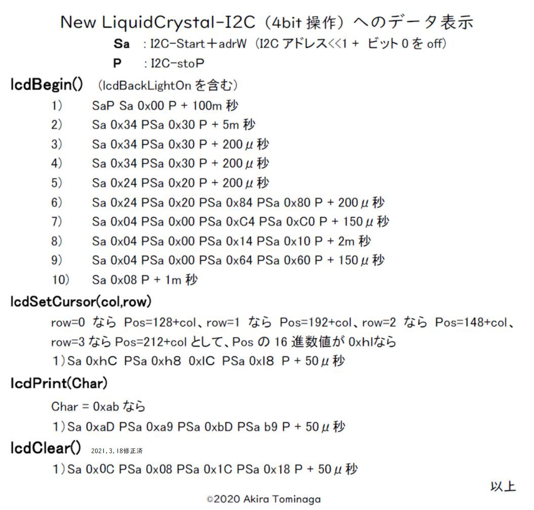
つまり、細かい検討をしなくともこの通りに作れば必ず動く!というわけです。
今回、PICは次のように配線することにします。毎度手書きのきたない回路図ですみませんが。今回はピンが限られたハードウェアI2C機構を用いず、RA3以外ならどのピンを使ってもOKとなるようにしました。

図に書いたLEDは今は必要がないので特につけていません。I2Cの汎用接続が他に使える利点に加えて、3つのピンが空いており、他のセンサー等を色々つけられます^^
マイコンの容量を消耗しないよう、こういうものはアセンブラーでうまく組みます。
;U201219-I2CLCD-V00.asm			     		As of Dec. 19, 2020
;;;;;;;;;;;;;;;;;;;;;;;;;;;;;;;;;;;;;;;;;;;;;;;;;;;;;;;;;;;;;;;;;;;;;;;;;;;;;;;;;
;										;
; 	Teting I2C-Liquid-Crystal-Display with PIC-12F1822 V00-00 		;
;	        (c)2020 Akira Tominaga, All rights reserved.			;
;	  Major revisions							;
;		00-00	Initial Version Dec.19, 2020				;
;										;
;	  Function								;
;		1.Show characters to LCD (New_LiquidCrystal_I2C 4bit op.)	;
;										;
;	  Input/output       							;
;		RA0 LED output when debugging					;
;		RA1 SCL for I2C  output						;
;		RA2 SDA for I2C  output  usually, and input occasionally	;
;										;
;	  Remarks								;
;		1. Clock = HFINTOSC (	16MHz)					;
;			Hence 1 step = 0.25 micro seconds			;
;;;;;;;;;;;;;;;;;;;;;;;;;;;;;;;;;;;;;;;;;;;;;;;;;;;;;;;;;;;;;;;;;;;;;;;;;;;;;;;;;
;
	list		p=12F1822      ; list directive to define processor
	#include	"p12F1822.inc" ; Device specific variable definitions
    __CONFIG _CONFIG1, _FOSC_INTOSC & _WDTE_OFF & _PWRTE_OFF & _MCLRE_OFF & _CP_OFF & _CPD_OFF & _BOREN_OFF & _CLKOUTEN_OFF & _IESO_OFF & _FCMEN_OFF
    __CONFIG _CONFIG2, _WRT_OFF & _PLLEN_OFF & _STVREN_OFF & _BORV_LO & _LVP_OFF
;	page
;;;;;;;;;;;;;;;;;;;;;;;;;;;;;;;;;;;;;;;;;;;;;;;;;;;;;;;;;;;;;;;;;
; 	Macro definitions					;
;;;;;;;;;;;;;;;;;;;;;;;;;;;;;;;;;;;;;;;;;;;;;;;;;;;;;;;;;;;;;;;;;
;
;;;;;;;;;;;;;;;;;;;;;;;;;;;;;;;;;;;;;;;;;;;;;;;;;
; 	Device dependent Macros			;
;;;;;;;;;;;;;;;;;;;;;;;;;;;;;;;;;;;;;;;;;;;;;;;;;
;*** Setting up PIC device ***
DEVset	macro
	BANKSEL	OSCCON		; Bank=1
	movlw	B'01111010'	; 16MHz and internal oscillator
	movwf	OSCCON
;
;	BANKSEL	INTCON		; Interrupt Con (in all banks hence comment)
	clrf	INTCON		; Disable all interrupts
;
; PORTA initialization
	BANKSEL	PORTA		; Bank=0
	clrf	PORTA
;	BANKSEL	LATA		; Bank=2
;	clrf	LATA
	BANKSEL	ANSELA		; Bank=3
	clrf	ANSELA		; No use of ADC
	BANKSEL	ADCON0		; Bank=1
	clrf	ADCON0		; No use of ADC
;
	BANKSEL	TRISA		; Bank=1
	movlw	B'11111000'	; RA0,1 and 2 are output
	movwf	TRISA
;
	BANKSEL	OPTION_REG	; Bank=1
	bcf	OPTION_REG,7	; Enable weak pull-up
	BANKSEL	WPUA		; Bank=4
	movlw	B'00111000'	; Weak Pull-up for RA3,4,and 5
	movwf	WPUA		;
;
	clrf	BSR		; Bank=0
	InitP			; Initialize ports
	endm
;
; *** Initializing IO ports ***
InitP	macro			; Initialize ports
	movlw	B'11111110'	; All IOs on, excluding RA0
	movwf	PORTA
	endm
;
;;;;;;;;;;;;;;;;;;;;;;;;;;;;;;;;;;;;;;;;;;;;;;;;;
; 	I2C Macros for genral purpose		;
;;;;;;;;;;;;;;;;;;;;;;;;;;;;;;;;;;;;;;;;;;;;;;;;;
; *** for I2C-Master protocol ***
; Sending data to I2C slave
I2Csnd	macro	slave,dataa,datalen
	movlw	slave
	movwf	I2Cadr
	movlw	dataa
	movwf	FSR0L
	movlw	datalen
	movwf	DataLen
	call	I2Csndr
	endm
;
; *** Receiving data from I2C slave ***
I2Crcv	macro	slave,dataa,datalen
	movlw	slave
	movwf	I2Cadr
	movlw	dataa
	movwf	FSR0L
	movlw	datalen
	movwf	DataLen
	call	I2Crcvr
	endm
;
; *** I2C start signal ***
I2Cstat macro
	call	I2Cstar
	endm
;
; *** I2C stop signal ***
I2Cstop	macro
	call	I2Cstpr
	endm
;
;;;;;;;;;;;;;;;;;;;;;;;;;;;;;;;;;;;;;;;;;;;;;;;;;
; 	I2C Macros for New_LiquidCrystal_I2C	;
;;;;;;;;;;;;;;;;;;;;;;;;;;;;;;;;;;;;;;;;;;;;;;;;;
; ***** for New LiquidCrystal-I2C *****
; *** Start I2C, send LCD adr, and get Ack, without stoP ***
LCDsA	macro
	call	lSndAr		; I2C start and send it
	endm
;
;*** Start, I2C,send LCD adr, and send Literal and stoP ***
LCDl	macro	lcdLit
	movlw	lcdLit
	call	lSndALr
	endm
;
; *** Set cursor (Col, Row) ***
LCDsetC	macro	Col,Row
 	if	Row==0
	movlw	H'80'+Col
 	endif
 	if 	Row==1
	movlw	H'C0'+Col
 	endif
 	if 	Row==2
	movlw	H'94'+Col
 	endif
 	if 	Row==3
	movlw	H'D4'+Col
	endif
 	if 	Row>3
	* row error *
	endif
	call	lSetCsr
	endm
;
; *** lcd.write a char ***
LCDw	macro	lcdChr
	movlw	lcdChr
	call	lSetChr
	endm
;
; *** lcd.clear() ***
LCDclr 	macro
	call	lClr
	endm
;
;;;;;;;;;;;;;;;;;;;;;;;;;;;;;;;;;;;;;;;;;
;	Time cosuming macros		;
;;;;;;;;;;;;;;;;;;;;;;;;;;;;;;;;;;;;;;;;;
Mic	macro			;Consume 1 μS only
	goto	$+1
	goto	$+1
	endm
;
Mic2	macro	mic2p		;Consume 2 μS x n
	movlw	mic2p
	call	Mic2r
	endm
;
Mic2p5	macro 	mic25p		; Consume 2.5μS x n
	movlw	mic25p
	call	Mic25r
	endm
;
Mic5	macro	mic5p		; Consume 5μS x n
	movlw	mic5p
	call	Mic25r
	movlw	mic5p
	call	Mic25r
	endm
;
Mic50	macro	mic50p		; Consume 50μS x n
	movlw	mic50p
	call	Mic50r
	endm
;
Milli	macro	millip		; Consume mS x n
	movlw	millip
	call 	Millir
	endm
;
Mil100	macro	mil100p		; Consume 100 mS x n
	movlw	mil100p
	call 	Mil100r
	endm
;
Secs	macro	secsp		; Consume Second x n
	movlw	secsp
	call	Secsr
	endm
;
Mins	macro	minsp		; Consume Minute x n
	movlw	minsp
	call	Minsr
	endm
;
;;;;;;;;;;;;;;;;;;;;;;;;;;;;;;;;;;;;;;;;;
;	Debug and Abend macros		;
;;;;;;;;;;;;;;;;;;;;;;;;;;;;;;;;;;;;;;;;;
LEDon	macro			; LED on macro for debugging
	BANKSEL	TRISdbg		; Select TRIS bank
	btfsc	TRISdbg,LED	; Is LED pin input?
	bsf	Flags,LEDpin	; Yes,show LED pin was input
	bcf	TRISdbg,LED	; Set LED output mode, in any case
	clrf	BSR		; Point Bank 0
	nop			; Timing for PORTdbg changed
	bsf	PORTdbg,LED	; LED on
	goto	$+1		; Timing for PORTdbg changed
	endm
;
LEDoff	macro			; LED off macro for debugging
	goto	$+1		; Timing in case PORTdbg changed
	bcf	PORTdbg,LED	; LED off
	btfss	Flags,LEDpin	; Was LEDpin input before debug?
	goto	$+7		; No, skip the followings
	BANKSEL	TRISdbg		; Select TRIS register
	bsf	TRISdbg,LED	; Set LED input mode again
	nop			; nop for timing
	BANKSEL	WPUdbg		; Bank for WPUx
	bsf	WPUdbg,LED	; Weak Pull-up for LED port
	clrf	BSR		; Point Bank 0
	nop			; Timing for PORTdbg changed
	endm
;
Udebug	macro 	Addr
	movf	Addr,W
	call	Udbgr
	endm
;
Trigon	macro			; DSO trigger on for debugging
	BANKSEL	TRISdbg		; Select TRIS bank
	btfsc	TRISdbg,Trig	; Is Trig pin input?
	bsf	Flags,Trigpin	; Yes, show Trig pin was input
	bcf	TRISdbg,Trig	; Set Trig output mode, in any case
	clrf	BSR		; Point Bank 0
	nop			; Timing for PORTdbg changed
	bsf	PORTdbg,LED	; Trig on
	goto	$+1		; Timing for PORTdbg changed
	endm
;
Trigoff macro			; DSO trigger off for debugging
	goto	$+1		; Timing in case PORTdbg changed
	bcf	PORTdbg,Trig	; Trig off
	btfss	Flags,Trigpin	; Was Trigpin input before debug?
	goto	$+7		; No, skip the followings
	BANKSEL	TRISdbg		; Select TRIS register
	bsf	TRISdbg,Trig	; Set Trig input mode again
	nop			; nop for timing
	BANKSEL	WPUdbg		; Bank for WPUx
	bsf	WPUdbg,Trig	; Weak Pull-up for Trig port
	clrf	BSR		; Point Bank 0
	nop			; Timing for PORTdbg changed
	endm
;
Uabend	macro	abn		; User Abnormal-end number
	movlw	abn
	goto	Uabendr
	endm
;
Ublink	macro	bno		; Blink LED for specified times
	movlw	bno
	call	Ublinkr
	endm
;
;;;;;;;;;;;;;;;;;;;;;;;;;;;;;;;;;;;;;;;;;;;;;;;;;;;;;;;;;;;;;;;;;
; 	Files and Equations					;
;;;;;;;;;;;;;;;;;;;;;;;;;;;;;;;;;;;;;;;;;;;;;;;;;;;;;;;;;;;;;;;;;
;
;;;;;;;;;;;;;;;;;;;;;;;;;;;;;;;;;;;;;;;;;
;	Files				;
;;;;;;;;;;;;;;;;;;;;;;;;;;;;;;;;;;;;;;;;;
	cblock	H'20'
; For Application support
	Abyte		; LCD I2C addr with R/W bit
	Dbyte		; Data byte to save Sbyte
	Ebyte		; The same purpose as Dbyte
	Wbyte		; Working byte
;
; For I2C protocols
	I2Cadr		; Destinated slave I2C address
	DataLen		; Number of bytes to be sent/received
	Sbyte		; One byte to be sent/received
	Bitctr		; Loop counter for bits in a byte
;
; Areas for time consuming subroutines
; Do not change the sequences from Mic5c to Minsc
;	if co-used with calculation parameters
	Mic25c
	Mic50c
	Millic
	Mil100c
	Secsc
	Minsc
;
; Areas for debugging routines
	DmpA 		; Display byte area
	Dmp8C 		; Bit counter for loop (Initial Dmp8V =8)
	BlinkC 		; Counter for blinking (set for Debugb or Abendb)
	Abendn		; Abend number
	Ucpc		; User Check point chr to trace
	Flags
	endc
;
;;;;;;;;;;;;;;;;;;;;;;;;;;;;;;;;;;;;;;;;;
; 	Equations			;
;;;;;;;;;;;;;;;;;;;;;;;;;;;;;;;;;;;;;;;;;
;;;;;;;;;;;;;;;;;;;;;;;;;;;;;;;;;
; 	For PORTA		;
;;;;;;;;;;;;;;;;;;;;;;;;;;;;;;;;;
;LED	equ	0		; PORTdbg LED  for debugging
;Trig	equ	0		; PORTdbg Trig for debugging
;Dl	equ	2		; PORTI2C SDA
;Cl	equ	1		; PORTI2C SCL
;
;;;;;;;;;;;;;;;;;;;;;;;;;;;;;;;;;
; ***	Logical PORTI2C		; Change this when port changed
;;;;;;;;;;;;;;;;;;;;;;;;;;;;;;;;;
PORTI2C equ	PORTA		;
Dl	equ	2		; I2C Data line = SDA
Cl	equ	1		; I2C Clock line = SCL
LATI2C	equ	LATA		; LATch for I2C port
TRISI2C equ	TRISA		; TRIS reg for I2C
;
;;;;;;;;;;;;;;;;;;;;;;;;;;;;;;;;;
; ***	Logical PORTdbg		; Change this when port changed
;;;;;;;;;;;;;;;;;;;;;;;;;;;;;;;;;
PORTdbg	equ	PORTA
TRISdbg	equ	TRISA
WPUdbg	equ	WPUA
LED	equ	0		; LED when debugging
Trig	equ	0		; Trigger for DSO when debugging
;
;;;;;;;;;;;;;;;;;;;;;;;;;;;;;;;;;
;	Values & Symbols	;
;;;;;;;;;;;;;;;;;;;;;;;;;;;;;;;;;
; Equations for LCD
LCDi2cA	equ	H'27'		; LCD I2C address (for Arduino)
lcdAw	equ	LCDi2cA*2	; LCD I2C address<<1 and Write
lcdAr	equ	LCDi2cA*2+H'01' ; LCD I2C address<<1 and Read
;
;;;;;;;;;;;;;;;;;;;;;;;;;;;;;;;;;
; 	For Debug		;
;;;;;;;;;;;;;;;;;;;;;;;;;;;;;;;;;
PORTdbg	equ	PORTA		;
Trig	equ	0		; DSO trigger pulse port for test use
;
Dmp8V	equ	D'8'		; Debug display bit counter initial value
Debugb	equ	D'8'		; number of blinkings to show Debugging
Abendb	equ	D'25'		; number of blinkings to notify Abend
; Flags byte
LEDsv	equ	0		; LED save bit in Flags byte
LEDpin	equ	1		; LED pin was input when not debugging
Trigpin	equ	2		; Trigger pin was input before debug use
;
	page
;;;;;;;;;;;;;;;;;;;;;;;;;;;;;;;;;;;;;;;;;;;;;;;;;;;;;;;;;;;;;;;;;
;	Initializing						;
;;;;;;;;;;;;;;;;;;;;;;;;;;;;;;;;;;;;;;;;;;;;;;;;;;;;;;;;;;;;;;;;;
	org	0
	goto	Startp		; Go to start entry
	org	4		; This is Interrupt entry
	retfie			;
;
Startp	DEVset			; Define ports
	clrf	FSR0H		; Clear FSR0H forever
	clrf	FSR1H		; Clear FSR1H forever
	clrf	Flags		; Clear all bits of Flags
;
	Milli	D'50'		; Wait devices stabilized
	call	LCDinir	 	; Set-up LCD
;
;;;;;;;;;;;;;;;;;;;;;;;;;;;;;;;;;;;;;;;;;;;;;;;;;;;;;;;;;;;;;;;;;
;	Main program loop					;
;;;;;;;;;;;;;;;;;;;;;;;;;;;;;;;;;;;;;;;;;;;;;;;;;;;;;;;;;;;;;;;;;
Mainp	equ	$
	LCDsetC	2,0
	LCDw	A'M'
	LCDw	A'e'
	LCDw	A'r'
	LCDw	A'r'
	LCDw	A'y'
	LCDw	A' '
	LCDw	A'C'
	LCDw	A'h'
	LCDw	A'r'
	LCDw	A'i'
	LCDw	A's'
	LCDw	A't'
	LCDw	A'm'
	LCDw	A'a'
	LCDw	A's'
;
	LCDsetC 8,1
	LCDw	A'a'
	LCDw	A'n'
	LCDw	A'd'
;
	LCDsetC 2,2
	LCDw	A'H'
	LCDw	A'a'
	LCDw	A'p'
	LCDw	A'p'
	LCDw	A'y'
	LCDw	A' '
	LCDw	A'H'
	LCDw	A'o'
	LCDw	A'l'
	LCDw	A'i'
	LCDw	A'd'
	LCDw	A'a'
	LCDw	A'y'
	LCDw	A's'
	LCDw	A'!'
;
	LCDsetC 9,3
	LCDw	A'('
	LCDw	A'8'
	LCDw	A'_'
	LCDw	A'p'
	LCDw	A'i'
	LCDw	A'n'
	LCDw	A'_'
	LCDw	A'P'
	LCDw	A'I'
	LCDw	A'C'
	LCDw	A')'
;
	Secs	1		; delay
	goto	Mainp		; Continue infinite loop
;
;;;;;;;;;;;;;;;;;;;;;;;;;;;;;;;;;;;;;;;;;;;;;;;;;;;;;;;;;;;;;;;;;
;	LCDini= LCD initializing routine			;
;;;;;;;;;;;;;;;;;;;;;;;;;;;;;;;;;;;;;;;;;;;;;;;;;;;;;;;;;;;;;;;;;
LCDinir	equ	$
	LCDsA			; Send LCD addr
	I2Cstop
;
	LCDl	H'00'		; Start,send adr & 0x00, and Stop
	Mil100	1
;
	LCDl	H'34'
	LCDl	H'30'
	Milli	5
;
	LCDl	H'34'
	LCDl	H'30'
	Mic50	4
;
	LCDl	H'34'
	LCDl	H'30'
	Mic50	4
;
	LCDl	H'24'
	LCDl	H'20'
	Mic50	4
;
	LCDl	H'24'
	LCDl	H'20'
	LCDl	H'84'
	LCDl	H'80'
	Mic50	4
;
	LCDl	H'04'
	LCDl	H'00'
	LCDl	H'C4'
	LCDl	H'C0'
	Mic50	3
;
	LCDl	H'04'
	LCDl	H'00'
	LCDl	H'14'
	LCDl	H'10'
	Milli	2
;
	LCDl	H'04'
	LCDl	H'00'
	LCDl	H'64'
	LCDl	H'60'
	Mic50	3
;
	LCDl	H'08'		; backlight on
	Milli	1
	return
;
;;;;;;;;;;;;;;;;;;;;;;;;;;;;;;;;;;;;;;;;;;;;;;;;;;;;;;;;;
;	LCD slave-adr sending routine			;
;	   	with address in Sbyte, getting Ack.	;
;		(start-I2C included, without stop-I2C)	;
;;;;;;;;;;;;;;;;;;;;;;;;;;;;;;;;;;;;;;;;;;;;;;;;;;;;;;;;;
lSndAr	equ	$
	I2Cstat			; start I2C
	movlw	lcdAw		; get LCD slave adr
	movwf	Sbyte		; set it to Sbyte
	call	Sendr		; and send it
	return
;
;;;;;;;;;;;;;;;;;;;;;;;;;;;;;;;;;;;;;;;;;;;;;;;;;;;;;;;;;
;	LCD I2C adr and a Literal sending routine	;
;;;;;;;;;;;;;;;;;;;;;;;;;;;;;;;;;;;;;;;;;;;;;;;;;;;;;;;;;
lSndALr	movwf	Dbyte		; save literal to Dbyte
	call	lSndAr		; send adr
	movf	Dbyte,W		; get saved literal
	movwf	Sbyte
	call	Sendr		; send it
	I2Cstop			; stop I2C
	return
;
;;;;;;;;;;;;;;;;;;;;;;;;;;;;;;;;;;;;;;;;;;;;;;;;;;;;;;;;;
;	Set-cursor routine for LCD called by lcdSetC	;			;
;	If W=0xab, send 0xaC, 0xa8, 0xbC, and 0xb8	;			;
;;;;;;;;;;;;;;;;;;;;;;;;;;;;;;;;;;;;;;;;;;;;;;;;;;;;;;;;;
lSetCsr	movwf	Ebyte		; save Value into Ebyte
	call	lSetCss 	; send left nibble
	swapf	Ebyte,W		; set W w/ swapping nibbles
	call 	lSetCss		; send right nibble
;
	Mic50	1
	return
;
; 	lSetCss subroutine to send a nibble
lSetCss movwf	Wbyte
	movlw	H'0F'
	iorwf	Wbyte,F		; set xF
	movlw	H'FC'
	andwf	Wbyte,W		; change it to xC
	movwf	Wbyte		; set it to Wbyte, too
	call 	lSndALr		; send S, adr, nibble+C, and P
;
	movlw	B'11111011'	; get complement of 0C-08
	andwf	Wbyte,W		; and change C to 8, ie x8
	call	lSndALr		; send S, adr, nibble+8, and P
	return
;
;;;;;;;;;;;;;;;;;;;;;;;;;;;;;;;;;;;;;;;;;;;;;;;;;;;;;;;;;
;	LCD send-char routine			;
;	If W=0xab, send 0xaD, 0xa9, 0xbD, and 0xb9	;
;;;;;;;;;;;;;;;;;;;;;;;;;;;;;;;;;;;;;;;;;;;;;;;;;;;;;;;;;
lSetChr movwf	Ebyte		; save Value into Ebyte
;	sending left nibble
	call	lSetChs
;
;	sending right nibble
	swapf	Ebyte,W		; replace left nibble w/ right
	call	lSetChs
	return
;
; 	LCD subroutine to send a character  ;
lSetChs	movwf	Wbyte		; W to Wbyte
	movlw	H'0F'		; set right nibble bits of
	iorwf	Wbyte,F		;   Wbyte on
	movlw	H'FD'		; leave left nibble + right D
	andwf	Wbyte,W		;  into W
	movwf	Wbyte		; save it into Wbyte
	call 	lSndALr		; send S, adr, nibble+D, and P
;
	movf	Wbyte,W
	movlw	B'11111011'	; target bit 2 to off (D to 9)
	andwf	Wbyte,W		; make left nibble + right 9
	call	lSndALr		; send S, adr, nibble+9, and P
	return
;
;;;;;;;;;;;;;;;;;;;;;;;;;;;;;;;;;;;;;;;;;;;;;;;;;;;;;;;;;
;	LCD.clear routine				;
;	Send 0x8C, 0x88, 0x0C, and 0x08			;
;;;;;;;;;;;;;;;;;;;;;;;;;;;;;;;;;;;;;;;;;;;;;;;;;;;;;;;;;
lClr	equ	$
	LCDw	H'8C'
	LCDw	H'88'
	LCDw	H'0C'
	LCDw	H'08'
	Mic50	1
	return
;
;;;;;;;;;;;;;;;;;;;;;;;;;;;;;;;;;;;;;;;;;;;;;;;;;;;;;;;;;
;	I2C Send byte-string for general purpose	;
;         when calling,					;
;		I2C device adr to be set in I2Cadr byte	;
;		Data length in DataLen			;
;		Data Addr in FSR0L (INDF0)		;
;;;;;;;;;;;;;;;;;;;;;;;;;;;;;;;;;;;;;;;;;;;;;;;;;;;;;;;;;
I2Csndr	movf	I2Cadr,W
	movwf	Sbyte
	bcf	Sbyte,0		; indicate write
;
	I2Cstat			; Start I2C
	call	Sendr

Sdata	movf	INDF0,W		; Get a sending character
	movwf	Sbyte		; Set it to Sbyte
	call	Sendr		; Send it to the device
;
	incf	FSR0L,F		; point next char
	decfsz	DataLen,F	; Have all chars sent ?
	goto	Sdata		; No, loop
;
; Stop signal and return
	I2Cstop
	Mic50	1
	return
;
;;;;;;;;;;;;;;;;;;;;;;;;;;;;;;;;;;;;;;;;;;;;;;;;;;;;;;;;;
; 	I2C Receive byte-string	for general purpose	;
;         when calling,					;
;		I2C device adr to be in I2Cadr byte	;
;		Data length in DataLen			;
;		Data Addr in FSR0L (INDF0)		;
;;;;;;;;;;;;;;;;;;;;;;;;;;;;;;;;;;;;;;;;;;;;;;;;;;;;;;;;;
I2Crcvr	equ	$
	I2Cstat			; Start I2C
	movf	I2Cadr,W	; Get I2C dev addr
	movwf	Sbyte		; Set it into Sbyte
;	rlf	Sbyte,F		; Shift left (if adr for Arduino)
	bsf	Sbyte,0		; indicate read
	call	Sendr		; Send slave addr to read
;
I2Crbyt	equ	$
	BANKSEL	TRISI2C		;
	bsf	TRISI2C,Dl	; Set Dline input mode
	clrf	BSR		; Point Bank 0
;
	movlw	8		; Bits in a reciving byte
	movwf	Bitctr		; into loop counter
I2Crblp	Mic5	1		; Timing before raising clock
	bsf	PORTI2C,Cl	; Set clock high
	Mic2p5	1		; Timing after raising clock
;
	btfsc	PORTI2C,Dl
	goto	Rbith
;	goto	Rbitl
;
Rbitl	bcf	Sbyte,0		; Clear bit 0
	goto	Rbitnxt		; and goto next
;
Rbith	bsf	Sbyte,0		; Set bit 0
Rbitnxt	Mic2p5	1		; Timing after checking
	bcf	PORTI2C,Cl	; Set clock low
;	Mic2p5	1		; Timing after clock falling
	decfsz	Bitctr,F	; Still bits?
	goto	Rbcont		; Yes, continue
	goto	Rbend		; No, end of one byte
;
Rbcont	rlf	Sbyte,F		; Shit left
	goto	I2Crblp		; and goto loop
;
Rbend	movf	Sbyte,W		; Get received byte
	movwf	INDF0		; Set it to INDF0
	incf	FSR0L,F		; increase index
	decfsz	DataLen,F	; DataLen-1
	goto	Sackr		; Send Ack and continue
	goto	Snackr		; Send Nack and stop
;
;Set Dl output mode and send Ack to conitinue
Sackr	equ	$
	BANKSEL	LATI2C		; Data line high when output mode
	bsf	LATI2C,Dl	; Lat-Dl on
	BANKSEL	TRISI2C		;
	bcf	TRISI2C,Dl	; Set Dl output mode
	clrf	BSR		; Point Bank 0
;
	bcf	PORTI2C,Dl	; Send Ack
	Mic2p5	1		; Timing after clock falling
	bsf	PORTI2C,Cl	; Show Ack
	Mic2p5	2
	bcf	PORTI2C,Cl	; Set clock low
	Mic2p5	1
	bsf	PORTI2C,Dl	; Return Dline to high
	goto	I2Crbyt		; Next byte process
;
;Set Dl output mode and send Nack
Snackr	equ	$
	BANKSEL	LATI2C		; Data line high when output mode
	bsf	LATI2C,Dl	; Lat-Dl on
	BANKSEL	TRISI2C		;
	bcf	TRISI2C,Dl	; Set Dl output mode
	clrf	BSR		; Point Bank 0
;
	bsf	PORTI2C,Dl	; Send Nack
	Mic2p5	1		; Timing after clock falling
	bsf	PORTI2C,Cl	; Show Nack
	Mic2p5	2
	bcf	PORTI2C,Cl	; Set clock low
	Mic2p5	2
	I2Cstop			; and stop I2C once
	Mic5	D'10'		; for 50 micro sec
;
	I2Cstat			; then start I2C again
	movf	I2Cadr,W	; Get I2C dev addr
	movwf	Sbyte		; Set it into Sbyte
	rlf	Sbyte,F		; Shift left
	bcf	Sbyte,0		; indicate write
	call	Sendr		; Send it
;
	I2Cstop
	return
;
;;;;;;;;;;;;;;;;;;;;;;;;;;;;;;;;;;;;;;;;;;;;;;;;;;;;;;;;;
;	I2C Start signal routine 			;
;	   	when dataline mode is output		;
;;;;;;;;;;;;;;;;;;;;;;;;;;;;;;;;;;;;;;;;;;;;;;;;;;;;;;;;;
I2Cstar	bcf	PORTI2C,Dl	; set SDA low
	Mic2p5	1
	bcf	PORTI2C,Cl	; set SCL low
	Mic2p5	3
	return
;
;;;;;;;;;;;;;;;;;;;;;;;;;;;;;;;;;;;;;;;;;;;;;;;;;;;;;;;;;
;	I2C Stop signal routine 			;
;	   	when dataline mode is output		;
;;;;;;;;;;;;;;;;;;;;;;;;;;;;;;;;;;;;;;;;;;;;;;;;;;;;;;;;;
I2Cstpr	bcf	PORTI2C,Cl	; set SCL low
	Mic2p5	1
	bcf	PORTI2C,Dl	; set SDA low
	Mic2p5	4
	bsf	PORTI2C,Cl	; Clock line rasing
	Mic2p5	2
	bsf	PORTI2C,Dl	; Data line rasing
	Mic2p5	1
	return
;
;;;;;;;;;;;;;;;;;;;;;;;;;;;;;;;;;;;;;;;;;;;;;;;;;;;;;;;;;
;	I2C One-byte sending routine + getting Ack	;
;	   	with data in Sbyte			;
;;;;;;;;;;;;;;;;;;;;;;;;;;;;;;;;;;;;;;;;;;;;;;;;;;;;;;;;;
Sendr	movlw	8		; Set bit count in a byte
	movwf	Bitctr		; into loop counter
;
Sloop	btfsc	Sbyte,7		; Check top bit of Sbyte
	goto	Slpdh		;
	bcf	PORTI2C,Dl	; If bit low then Data L
	goto	Slpnxt
Slpdh	bsf	PORTI2C,Dl	; If bit high then Data H
;
Slpnxt	Mic2p5	1
	bsf	PORTI2C,Cl	; Show bit
	Mic2p5	2
	bcf	PORTI2C,Cl	;
	Mic2p5	1
;
	rlf	Sbyte,F		; Shift left
	decfsz	Bitctr,F        ; All bits done?
	goto	Sloop		; No, loop within a byte
;
;Receive Ack
; set data line input mode
	BANKSEL	TRISI2C		;
	bsf	TRISI2C,Dl	; Set Dline input mode
	clrf	BSR		; Point Bank 0
;
	Mic2p5	1		; wait for Ack timing
	bsf	PORTI2C,Cl	; Clock H for Acq confirmation
	Mic2p5	2		;
	bcf	PORTI2C,Cl	; Cl L for Dl release by slave
	Mic2p5	2
;
; Set Data line output
	BANKSEL	LATI2C		; Data line high when output mode
	bsf	LATI2C,Dl	; Lat-Dl on
	BANKSEL	TRISI2C		;
	bcf	TRISI2C,Dl	; Set Dl output mode
	clrf	BSR		; Point Bank 0
	return
;
;;;;;;;;;;;;;;;;;;;;;;;;;;;;;;;;;;;;;;;;;;;;;;;;;;;;;;;;;;;;;;;;;
;	Timing subrooutines for general purposes		;
;;;;;;;;;;;;;;;;;;;;;;;;;;;;;;;;;;;;;;;;;;;;;;;;;;;;;;;;;;;;;;;;;
;
;;;;;;;;;;;;;;;;;;;;;;;;;;;;;;;;;;;;;;;;;;
; 	Make 2.0 micro S x n	(Mic2)	;
;;;;;;;;;;;;;;;;;;;;;;;;;;;;;;;;;;;;;;;;;
Mic2r	movwf	Mic25c		; + Wset + call = 1 micro sec
;
Mic2l	decfsz	Mic25c,F	; If exhausted, 1 micro S hereafter
	goto	Mic2li		; else go out (2nd time 1.75 mic sec)
	return
;
Mic2li	goto	$+1		;            (2nd time 2.25 mic sec)
	nop			;	     (2nd time 2.5 mic sec)
	goto	Mic2l		; go back    (2nd time 3 micro sec)
;
;;;;;;;;;;;;;;;;;;;;;;;;;;;;;;;;;;;;;;;;;
; 	Make 2.5 micro S x n (Mic2p5)	;
;;;;;;;;;;;;;;;;;;;;;;;;;;;;;;;;;;;;;;;;;
Mic25r	movwf	Mic25c		; + Wset + call = 1 micro sec
	nop			; 1.25 micro sec
;
Mic25l	nop			; 1.5 micro sec (2nd time 4 mic sec)
	decfsz	Mic25c,F	; If exhausted, 1 micro S hereafter
	goto	Mic25li		; else go out (2nd time 2.25 mic sec)
	return
;
Mic25li	Mic			;	      (2nd time 3.25 mic sec)
	goto	Mic25l		; go back    (2nd time 3.75 micro sec)
;
;;;;;;;;;;;;;;;;;;;;;;;;;;;;;;;;;;;;;;;;;
;	50 Microseconds	x n	Mic50  	;
;;;;;;;;;;;;;;;;;;;;;;;;;;;;;;;;;;;;;;;;;
;
Mic50r	movwf	Mic50c	 	; set how many 50 microsec (1 micro sec to here)
	nop			; 1.25 micro sec up to here
;
Mic50l	Mic2p5	D'19'		; + 47.5 = 48.75 mic sec (2nd time 98.75 mic sec)
	nop			; + 0.25 = 49 micro sec (2nd time 99 mic sec)
;
	decfsz	Mic50c,F	; If exhausted then 1 mic S hereafter
	goto	Mic50li		; else go out (2nd time 49.75 mic sec)
	return
;
;
Mic50li	Mic			; 	  (2nd time 50.75 mic sec)
	goto	Mic50l		; go back (2nd time 51.25 mic sec)
;
;;;;;;;;;;;;;;;;;;;;;;;;;;;;;;;;;;;;;;;;;
;	Milliseconds x n	(Milli)	;
;;;;;;;;;;;;;;;;;;;;;;;;;;;;;;;;;;;;;;;;;
;
Millir	movwf	Millic 		; set how many 1 mil sec (1 mic S up to here)
	nop			; 1.25 micro sec
;
Millil	Mic50	D'19'		; + 50 mic x 19 = 951.25 mic S (2nd, 1951.25)
	Mic2p5	D'19'		; + 47.5 mic = 998.75 micro S  (2nd, 1998.75)
	nop			; +0.25 mic = 999 micro sec    (2nd, 1999)
;
	decfsz	Millic,F	; If  exhausted then 1 micro sec hereafter
	goto	Millili		; else go out (2nd, 999.75 mic S)
	return
;
Millili	Mic			; 		(2nd time 1000.75 mic S)
	goto	Millil		; go back (2nd time 1001.25 mic S)
;
;;;;;;;;;;;;;;;;;;;;;;;;;;;;;;;;;;;;;;;;;
;	100 Milliseconds x n	(Mil100);
;;;;;;;;;;;;;;;;;;;;;;;;;;;;;;;;;;;;;;;;;
Mil100r	movwf	Mil100c		;set how many 100 ms(1 micr sec up to here)
	nop			; 1.25 micro sec
;
Milhl	Milli	D'99'		;+1ms x 99 = 99001.25 micS (2nd,199001.25mic)
	Mic50	D'19'		; + 950 mic = 99951.25 micS(2nd.199951.25mic)
	Mic2p5	D'19'		; + 47.5 mic = 99998.75micS(2nd,199998.75mic)
	nop			; + 0.25 mic = 99999 mic S (2nd,199999 micS)
;
	decfsz	Mil100c,F	; If exhausted then 1 micro sec hereafter
	goto	Milhli		; else go out (2nd time, 99999.75 mic S)
	return
;
Milhli	Mic			;  	    	(2nd time, 100000.75 mic S)
	goto	Milhl		; 		(2nd time, 100001.25 mic S)
;
;;;;;;;;;;;;;;;;;;;;;;;;;;;;;;;;;;;;;;;;;
;	Seconds x n	 (Secs)		;
;;;;;;;;;;;;;;;;;;;;;;;;;;;;;;;;;;;;;;;;;
;
Secsr	movwf	Secsc 		; set how many sec ( 1 mic sec up to here)
	nop			; 1.25 micro sec
;
Secsl	Mil100	D'9'		;
	Milli	D'99'		; + 999 milli sec = 999001.25 micro sec
;
	Mic50	D'19'		; + 950 mic = 999951.25 micro sec
	Mic2p5	D'19'		; + 47.5 mic = 999998.75 micro sec
	nop			; + 0.25 mic = 999999 micro sec
;
	decfsz	Secsc,F		; If exhausted then 1 micro sec hereafter
	goto	Secsli		; else, go out
	return
;
Secsli	Mic
	goto	Secsl		; (Second time, Sec + 1.25 micro sec)
;
;;;;;;;;;;;;;;;;;;;;;;;;;;;;;;;;;;;;;;;;;
;	Minutes	x n	 (Mins)		;
;	 Overhead ignored, that is only	;
;	 751.25 Mic S even when 100 Min	;
;;;;;;;;;;;;;;;;;;;;;;;;;;;;;;;;;;;;;;;;;
Minsr	movwf	Minsc		;set how many minutes from parameter
;
Minsl	Secs	D'60'		; 1 Seconds x 60
	decfsz	Minsc,F
	goto	Minsl
	return
;
	space
;;;;;;;;;;;;;;;;;;;;;;;;;;;;;;;;;
; User debug subroutine		;
;	Show bit 7 to 0 	;
;	of specified byte	;
;;;;;;;;;;;;;;;;;;;;;;;;;;;;;;;;;
Udbgr	clrf	BSR		; Set Bank=0
	movwf	DmpA		; move data to Dmpa
;
	btfss	PORTdbg,LED	; Check if LED=on (on=High)
	goto	UdbLoff		;  if LED=off(Low), skip saving process
	bsf	Flags,LEDsv	; Save LEDon status
	LEDoff			; and off LED
	Mil100	D'10'		; wait for a second in case LED has been on
;
UdbLoff	movlw	Dmp8V		; set counter 8
	movwf	Dmp8C		; to Dmp8C
;
Udblp	Ublink	Debugb		; Blink for Debug = 8 times
	btfsc	DmpA,7		; check top bit 7
	goto	UdbOn		; if on then to UdbOn
	goto	UdbOff		; if off then to UdbOff
;
UdbOn	LEDon
	Mil100	D'30'		;
	goto	Udbeck
;
UdbOff	LEDoff
	Mil100	D'30'		;
;	goto	Udbeck
;
Udbeck	decfsz	Dmp8C,F
	goto	Udbnext
	goto	Udbend
;
Udbnext	rlf	DmpA,F
	goto	Udblp
;
Udbend	Ublink	Debugb		; end blinking and
	Mil100	D'100'		; blank for 10 seconds to write down
;
	btfss	Flags,LEDsv	; Check if LED was on
	goto	Udbret		;  no, goto return
	LEDon			;  if it was on, then on again
	bcf	Flags,LEDsv	; Clear LED save flag
;
Udbret	return
;
;;;;;;;;;;;;;;;;;;;;;;;;;;;;;;;;;;;;;;;;;
; Blinking to show debug or abend	;
;;;;;;;;;;;;;;;;;;;;;;;;;;;;;;;;;;;;;;;;;
Ublinkr	movwf	BlinkC
Ublinkl	LEDon			; LED on
	Milli	D'30'		; for 30ms
	LEDoff			; LED off
	Milli	D'200'		; for 200ms
;
	decfsz	BlinkC,F
	goto	Ublinkl
	return
;
;;;;;;;;;;;;;;;;;;;;;;;;;;;;;;;;;;;;;;;;;
; 	Abend routine			;
;;;;;;;;;;;;;;;;;;;;;;;;;;;;;;;;;;;;;;;;;
Uabendr	clrf	BSR
	movwf	Abendn			; Set Uabend number
;
	Ublink	Abendb			; Blink 25 times
	Udebug	Abendn			; Show Abend number
	goto	$
;
;;;;;;;;;;;;;;;;;;;;;;;;;;;;;;;;;;;;;;;;;;;;;;;;;;;;;;;;;;;;;
;	End of program						;
;;;;;;;;;;;;;;;;;;;;;;;;;;;;;;;;;;;;;;;;;;;;;;;;;;;;;;;;;;;;;
	end
上のコーディングでは他のI2Cセンサーがつけられるよう汎用I2C対応ができるようにしています(ただしRead String部分は未テスト。とはいえ、1バイトずつ読めばなくてもよいですし)。このLCDではもちろんReadは要りませんが。
ディスプレイが使えることで要らなくなったデバッグ用のコーディング部分(最後のほう)もそのまま含めています。ここはすっぽり外して問題ないもの。
全体594命令から不要なデバッグ用コードをはずせば、僅か350命令です。プログラム容量(2048ワード)の17%に収まります。また、RAMメモリーは128バイトのうち、デバッグ用も含めて20バイトしか使っていませんので、RAM容量も16%未満に収めることができました。
これで、今後小型PICからも楽に使えることになったので、今回週末を使った甲斐がありました\(^o^)/。
センサー装置の基盤としてはコスパ最高かも。なにせ1602LCDの場合なら300円ほどでできる環境ですから。
この記事がもしどなたかのお役に立つようであれば幸いです。
©2020 Akira Tominaga, All rights reserved.